This is an on-going page detailing a A ‘Proper’ Koi Pond from start to finish in 2009 that commenced 01/06/09 and will be updated as and when every stage is completed.
The total system will hold around 15,000 gallons (68 tons) and has been designed on new ground with views from the house, which is also being built. It is unimportant as to the actual physical size of this pond as the stages, which will all be detailed, apply to any size of a ‘proper’ system that can be installed today.
(This page of information is intended for serious Koi enthusiasts, as a result there no pond liners, no ‘pump-fed’ principles, no ‘retro drains’ – because all are a complete waste of time of money as covered earlier, once again, they are all incredibly useless. As far as wonderful final landscaping is concerned, especially if one has to live with the final view for many years to come, this is of paramount importance even though it is only ‘icing on the cake’. It is an in-ground design just like all ponds are in the real world – there are, most definitely, no glass aquarium windows anywhere nor are there the first few stories of a mini tower block in the centre of the lawn which are there as the result of saving a day or two more in excavation. Sorry, I thought I’d mention this rather than waste anyone’s time in following all this.)
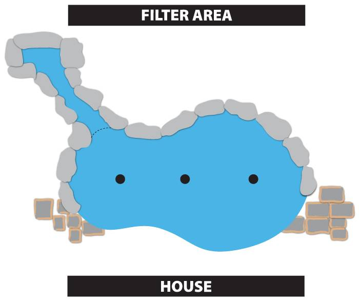
This is the design I came up with that met with both the approval of the Koi keeper and his wife – (most important). The final landscaping between the pond, the waterfall and filter will be in keeping with the large boulders as seen on the plan. This should give a pleasant backdrop to the pond when viewed from the house. The front area between the pond and house will be flat and paved. The paving stones will be cut to shape to give a clean geometrical curve to the pond edge.
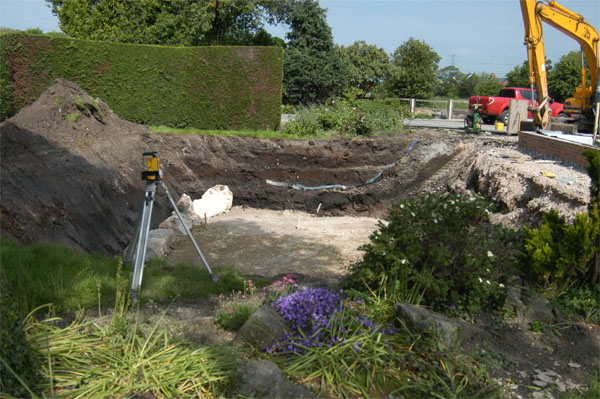
01/06/09 – The digger and its operator carried out the excavation in less than four hours and the topsoil has been saved for final pond landscaping. The other waste was distributed on nearby land to be landscaped later. This shows the pond area only which has been excavated in excess of requirements for ease of building. The final pond water depth will be 2 metres and so the depth of the excavation was made 2.3 metres below final water level to allow for the base thickness.
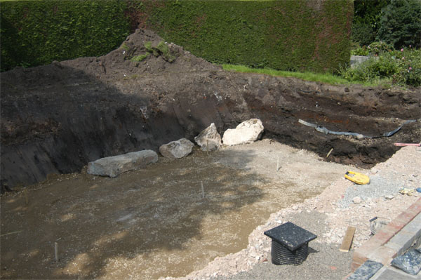
The boulders found (picture 2) were of no use for landscaping so they have been left in place to be buried. The entire flat base area was packed down by machine with crushed hardcore ground down from nearby outbuildings that were no longer needed and had to be demolished. The filter system will be built next to the mound of topsoil seen here on the left of the picture below.
02/06/09
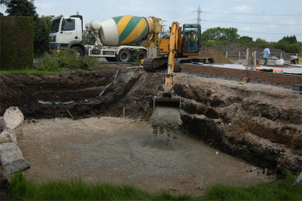
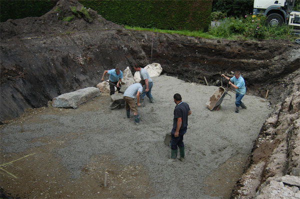
The prime 15cms base to the entire area was made by delivery truck as shown here.
This shows the concrete being distributed evenly across the entire base area. We need big lads for this work!
09/06/09
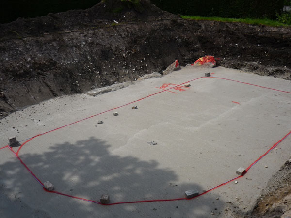
After the base had set, the outline of the pond shape was made by red spray paint as shown. The ‘gateway’ shown in red marker is where a trench will be made to run the drain lines to the filter area. The boulders are now partially covered. Final landscaping later will alter the straight-edged pond walls seen here.
10/06/09
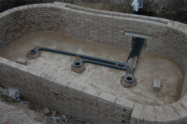
The pond walls were commenced to finish just below the level where the five return lines will be fitted later – at 70cms below water level as shown at the top of the pond walls here. The three drains and drain air supplies were installed on 12/06/09. The rectangle left in the pond wall is to allow all the drain lines and air diffuser lines to pass through to the filter area. After this the space will be bricked-in as part of the pond wall. After the drain sumps were checked to be level they were secured carefully with concrete to prevent them from moving when the second base is cast.
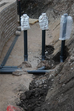 The three four inch pressure lines from each drain to the filter system are connected by four inch, long radius bends in order to minimise friction-loss in water supply although in this example 4” 90 degree elbows will do as flow rate required is not so great.
A word here, almost everyone can fix pipework and fittings together with solvent cement but doing this apparently simple task ‘properly’ is not really so simple – especially when larger bore pipelines are used – generally one only has one chance!
This shows the three four inch drain lines and the three one-inch airlines after exiting the pond. These are cut to approximate length and each will supply pond water to its own filter and then be taken back to the pond by its own pump. This is my ‘One Drain to One Filter to One Pump’ principle first introduced in 1991 and described earlier. This is still the only way possible to ensure that each drain is operating as required in any ‘multi-drain system’.

