(Some of this is continued from ‘Filter Boxes’ on the previous page but in greater detail.)
Whilst the information on this page is aimed at our biological stages of the filter boxes rather than the mechanical stages, some of it will ‘overlap’ naturally. However, I am trying to outline here how best to harness and pass ‘ammonia-rich’ water produced by our Koi over ‘surfaces’ that are positioned and contained within our boxes. We need to supply ALL of these surfaces with a constant supply of ‘food’ at an equally constant flow rate/retention time/dwell time per square inch/square centimetre per minute. If we can manage to achieve this ‘flow pattern’ with some high percentage of success, it is only then that we can begin to determine the ideal ‘flow rate’.
To make a comical comparison here, a flow-rate that is too slow transforms delicious, piping hot food into a cold, tasteless and unpalatable mess, whilst a flow-rate that is too fast is similar to attempting to grab a very small sandwich from a person standing on the roadside whilst driving by at ninety miles per hour.
More to the point, in order to make the contents of our various box dimensions as efficient as is humanly possible – and thereby economise on ground space, we need to supply ALL the surfaces within our boxes (irrespective of size) rather than just a small percentage of them. This is not nearly as simple as it may appear to be, I have personally ‘Chased Nirvana’ for many years and have come up with many seemingly perfect ways of attempting to harness this natural element that usually shrugs-off discipline. In truth, most have been flawed but still the challenge remains.
I really do believe I have come up with the very best possible way of achieving this as of right now but, before I attempt to detail this, it is very important to cover all other popular attempts and methods that are still in use today as well as earlier attempts that fell by the wayside in bygone times.
1. Flow Patterns
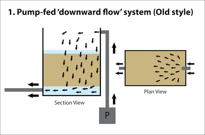 This was the first attempt at pond water filtration and was promoted by the production of ‘Black Boxes’ still sold in their thousands today by garden centres to unsuspecting beginners who have decided to build their first pond.
Water is pumped from the pond into the top of a box that contains a barrier as shown. It falls through the barrier and then empties out of the box by falling back into the pond. The idea was that the media barrier would ‘purify’ the incoming water by trapping all the ‘visible nasties’ that contributed to dirty pond water. In those days the word ‘ammonia’ was never even considered nor understood – only the word ‘clarity’ was important. There were further developments of this whereby spray-bars and filter floss were employed to provide greater water distribution and greater trapping ability of larger solids. However, the idea was to supply all surfaces of the barrier with an equal supply of contaminated water at an equal flow rate. Alas water ‘falls’ at varying levels and it also finds its easiest way down-wards, as a result, open and easy ‘channels’ formed inside the media where the majority of water ‘tracked’ on its way down. These channels soon became clogged with debris and so easier channels had to be found. If total, messy and laborious cleaning was not carried out at very regular intervals, all channels clogged. When this situation came to be, the barrier struggled to allow the entire incoming water to pass at the required rate and so the majority of the incoming water found another, far-easier, exit point from the box by way of overflowing onto the surrounding garden and draining the pond at the same time. Soon the water pump burned-out and the owner returned to find his fish floundering in the small indentations that were the deepest parts of his pond. This was soon resolved by an unknown and forgotten plumber of the day, he came up with the ingenious idea of putting an overflow at the top of the box to take excess water back to the pond and thus give safety to both pump and fish and it worked as promised by doing just that! As a result, these wonders could then be left unattended forever – and they were. After a period of time the entry water found it far easier to by-pass the complex gravels below and simply directed supply straight to the overflow exit. In turn, the media had no water passing through it now and decided to set like concrete. As mentioned earlier, the derivatives of these Black Boxes, complete with U/V and ‘guarantee’ sell all over the world in their thousands despite the fact they can never even begin to filter our ponds.
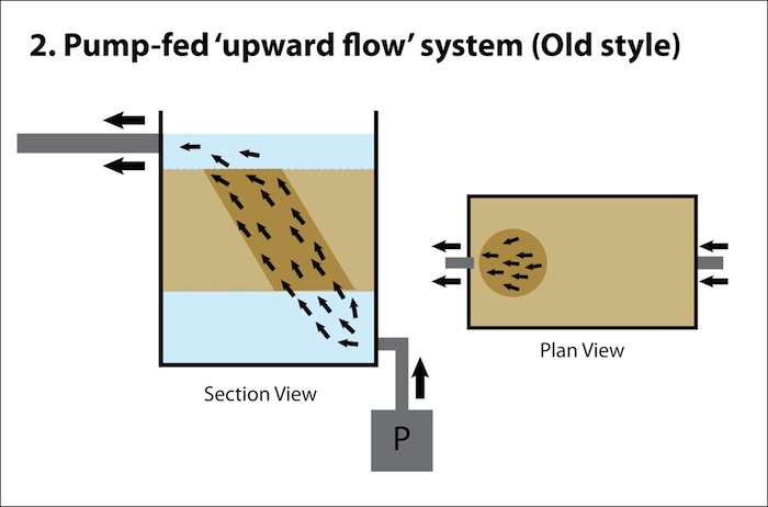 I designed this system and first offered it for sale in 1979 after first getting a very small understanding of the ‘nitrification process’.
It was a tall, circular tube of 15” diameter made from polypropylene. I reasoned that ‘upward-flow’ water would rise at a constant level rather than fall at different levels.
I thus convinced myself that all media surfaces (gravels in those days) would be supplied at a constant flow of incoming water and perfection would follow. Alas, I was wrong and the diagram shows why. The incoming water has ‘impetus’, ‘movement’ or ‘force’ behind it which is produced by the pump delivery outlet below. As a result, this added ‘power’ enters the box and directs itself immediately to the outlet at the top of the box in order to exit as quickly as possible. Thus ensues ‘tracking’ and the channel shown in darker colour shows maximum ‘initial’ biological performance. I say ‘initial’ because soon those channels clogged and other channels were formed and so on. At my estimation, only 10% of the box was even mildly efficient, a call to return to the drawing board then beckoned to me!
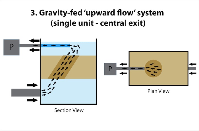 I first introduced the gravity-fed principle to the then, tiny Koi public in 1981. This remains to be the ONLY real way to provide pond water to a filter box today.
The incoming water is supplied directly from the pond drain in 4” bore tube by simple ‘gravity’. This obviously necessitates that both pond and filter water levels are identical.
This painfully simple yet incredibly effective principle transformed Koi pond design at the time and disposed of all traces of unsightly pumps, electric mains leads and large-bore hoses being visible within our ponds. All of this ‘plumbing tackle’ could now be concealed from view near our filter boxes. Instead all we were left with was what we really wanted – namely water and Koi only – perfection, well……..nearly!
This particular sketch shows a central exit suction inlet ‘off-take’ to the pump and it is almost impossible to ever achieve perfection with any of these designs but I will attempt to do so over the next few examples. Whilst the upward-flow principle is ‘almost perfection’ in theory when the water levels are static and equal (it has to be), this is all utterly destroyed and trashed the very moment the pump is switched on for the very first time. Again, incoming water has force and impetus and thus ‘tracking’ comes back into its own. The next illustrations only show different pump pick-up points that have been employed over the years to attempt perfection, sadly all are flawed. For the above example – how about only 15% of the box volume is being utilised?
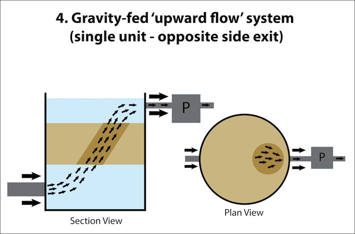 There should be no real need for an explanation here as this shows example 3 without the central off-take and this is replaced by a side, ‘overflow-off-take’ at the other side of the box to the incoming water.
15% maximum efficiency again?
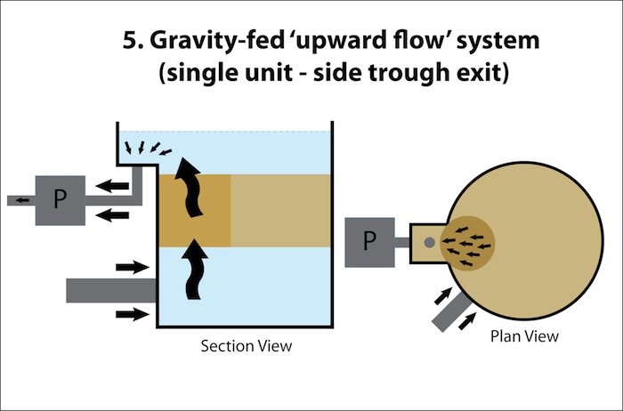 In recent years, a side trough/box has been included where the pump suction inlet is connected has employed this off-take method. I have never seen the point of this design, as the trough is merely an overflow to the main box that has an obviously identical water surface level.
Again, the same percentage of box efficiency as the one shown in examples 3 & 4 possibly?
Whilst on the subject as to finding a perfect way of taking water from the surface of a container whilst allowing the rising water within the container to rise as water does, thereby supplying all media surfaces as required – no matter where pipeline supplying the suction inlet of the pump is inserted or placed, ‘tracking’ will begin once the pump is started. Again, the momentum of incoming water produces this ‘tracking’ whilst the suction of the pump inlet further beckons the incoming water flow towards it when it is then taken into the pump.
Furthermore, and this is VERY important, the invisible channel formed as a result of the water tracking cannot possibly be improved upon or increased in size even by the heaviest of added water jets or aeration to disturb this in the hope of distributing more water to supply to areas within the box that are outside of the invisible channel. Whilst it will provide aeration and disturbance to all water and surfaces within the container, the invisible channel will continue its path completely undisturbed and so the ‘box potential’ remains to be inefficient.
 Although this example is the most efficient way I know of to take surface water from a box and use a better performance than the earlier examples above, it is, nonetheless, a compromise that still only performs to around 25% of the box itself. Please do not try this at home as it incorporates PRECISE horizontal levels in the making and siting of the box and also incorporates level switches to control the pump and expensive electrical switchgear to regulate the incoming water supply when the rare need arises. In short, it is a costly nonsense that only produces 10% more efficiency than the earlier examples – but it is an improvement all the same which makes the earlier box examples even less attractive as a serious proposition.
As shown in the layout, the inner box chamber finishes just below final water level of the pond surface. Another trough is constructed all around the box, which finishes slightly above pond water level. The depth, width and level position of the trough can be tailored to suit as required. Providing the box sits PERFECTLY level and the inner box top is also EXACTLY level, then incoming gravity-fed water will reach the top level of the inner box and cascade over all the top of the box equally producing a waterfall effect to all perimeters of the inner box. This water will fall into the trough below and, if no pump is switched on, will simply rise to the water level of the pond and stop. The pump suction inlet can then be taken from any part of the underside or side of the trough and switched on. Once the trough level falls below the inner box level, the waterfall supplied by the incoming water as in any gravity-fed application will then replace this and thus the system continues in its mediocrity.
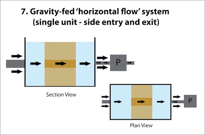 This is an example of passing water through a box in a horizontal direction. Once again, this is no better than the earlier examples as incoming water, with impetus, is sucked towards the exit by the pump. As a result, the central core of the media is the only part of it that receives constant water flow. Again, only 15% efficiency of box.
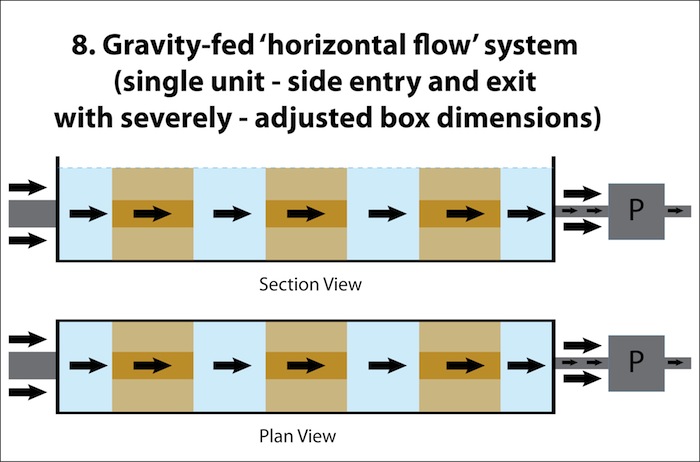 This is the exactly the same water flow as above but applied to a longer, shallower and narrower box which also holds three smaller media barriers rather than a single large one. Water still continues to ‘track’ as shown but the invisible pipeline remains to be the same ‘outer bore’. This does produce a longer travel throughout the three barriers, which is a marginal improvement, but not worth mentioning as it still only produces a 20% overall efficiency.
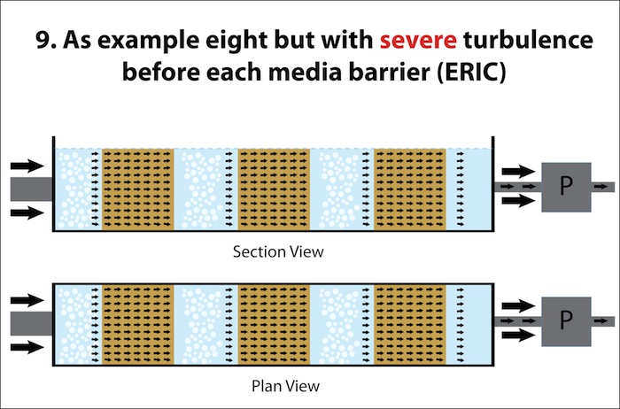 Exactly the same as in example eight but now the narrow and shallow spaces before each media barrier are ‘battered’ with severe and constant turbulence all along the base width of these empty spaces with a curtain of air and this transforms the entire performance of the system.
(Incidentally, the smaller the spaces are before the cartridges, the better the captive disturbance operates.)
The normally invisible pipeline between the inlet and the pump no longer is present as such in this instance due to the very narrow and shallow box dimensions and the relatively short runs of travel before each media barrier. These empty spaces now confuse the incoming water supply and no longer do normal ‘layers’ exist. Furthermore, despite the reduced surface area of a single large media barrier, we can now use three separate media barriers that are greater in length albeit reduced in width and depth. If box dimensions are rigidly kept to and maximum aeration is applied, then this flow pattern, within this box produces almost 70% efficiency, thus the water moves forward constantly as a ‘BLOCK’. The media barriers employed within the box (that can be now referred to as ‘a river’) then further increase this flow efficiency to over 90% – not quite perfection – but close enough if compared to the other alternatives that are available!
 However, it is a clever combination of several vital necessities and principles that go towards making this system so efficient. The painfully simple, yet well-designed box and its specific dimensions are one; the horizontal-flow pattern is another; the significant aeration additions prior to each media barrier are another; and so are the media barriers themselves that have been chosen and tailored exactly to size for maximum, useable biological surfaces within each river.
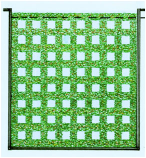
This is a scale illustration of the face view of one of the cartridges used in a standard river and this is what the block of water faces three times along its travels. As you can see, it is not possible for even one drop of water to avoid these barriers. It cannot pass under, above or on either side, instead it must travel through to reach the pump at the end. The cartridge form seen here is dictated by the thickness of the material, which is supplied in flat sheets of 2 metres by 1 metre. By exact spacing of the thin fillets, 64 open channels are produced on the finished cartridge and the aim is to supply every channel with a constant flow of ammonia-rich water. As with any inert surface fed with a constant supply of dissolved ammonias within the water flow, aerobic bacteria will colonise initially and then go on to form a significant biomass on all the surfaces within its path. Once matured, this will process our incoming water supply perfectly and allow it to return to our ponds free from dissolved toxins. Whilst the flat sheet material is a superb material that allows for permanent submersion in water, the true ‘magic’ of it can only be realised when tailored to these specific dimensions.
2. Flow Rates
I do not know exactly who first came out with information specifying ‘desired flow rates’ or ‘dwell times’ along media surfaces for biological fish pond filtration but I do know one thing and this was that he/she assumed that ALL the surfaces within a specific box were being presented with a constant and endless supply of nutrients for the ALL the biomass within the box.
‘Assumption’, in this instance, is extremely dangerous, as we all know now by the examples given above where neither of the requirements apply – apart from example nine. Nor am I sure at all, that the same person/s writing this information ever achieved his/her assumptions in real-life, practical applications. Unless, that is I therefore also to ‘assume’ that he/she was using some early derivative of ERIC in the trials that were to produce this information for us all?
In view of the above, I can only advise my flow-rate requirements for a standard ERIC unit which is that the pond volume is passed through the box every 2.5 hours as an approximation in order to produce excellent results. This time specified can be adjusted a little either way but I would certainly not advocate less than 2 hours or more than 3 hours so experiments can be made with each individual pond. Also, by slightly increasing the length of a concrete version and retaining the same width and depth dimensions, a further cartridge can be added and this will allow for a greater flow rate for a pond with a larger volume. Without complicating the issues surrounding these principles, even minor width and depth adjustments (smaller or larger) to the box dimensions can change performance possibilities significantly. As covered in detail on another page, the perfect performance of bottom drains also rely greatly on the flow rate through our filter boxes.
Before releasing this page I have checked and re-checked the information to find it reads exactly as intended. Furthermore I have only detailed the truth as I see things, if it does put another slant and further thoughts on these subjects to some out there then it has hit the desired mark.

