System Operation
The system has been designed to have two separate pumping systems – identical to the smaller system covered on the earlier page.
One system is that the three filter lines fed by the bottom drains will operate permanently 24/7 with no other equipment incorporated in the open return 2” lines back to the pond and in the shortest open pipe runs possible.
The second system is fed by two custom-built surface skimmers which provide water to two external pumps before both of their return lines pass through separate U/V units and electric heaters units before then being returned to the waterfall/stream for final return to the pond. The waterfall/stream will be turned off in cooler periods and the water will be re-directed straight to the pond by control valves built into the return lines. As this second system has nothing to do with the water filtration and drain operation, timers can be fitted to skim and operate the waterfall/stream for, say three hours per day; the U/V’s can be switched on when required to remove green water periods; the heaters are there to avoid potential disasters that may be present in very cold ambient air temperatures.
All this will be detailed later as work progresses.
16/06/09
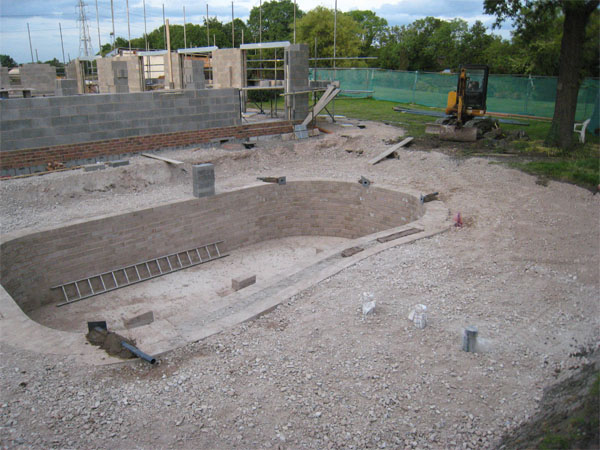
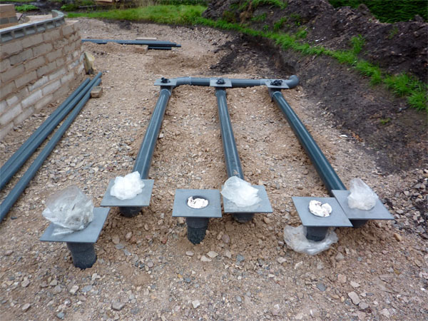
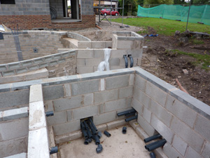
The area surrounding the pond has now been partially back-filled and the pond walls have stopped until the five return line stubs have been inserted at the required angles. The three lines coming out from the bottom drains can be seen to the right.
The blocks piled on the left side of the pond show final water level of the system.
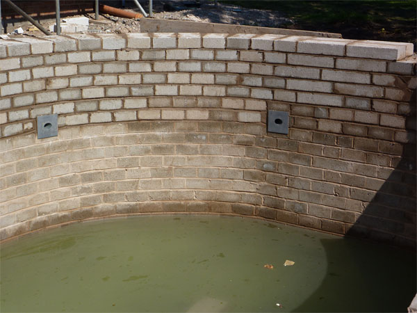
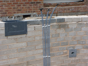
This is a detailed shot of two return lines that have been fabricated with an end plate at the required angle of pond entry to produce good clockwise currents to the pond. When the inner walls have been completed, these plates make it easier for smooth wall finish, smooth glass laminating and watertight seals. These will be encased in block work as the walls continue.
Incidentally all drains and pipelines have been expertly fitted to this system by Matt Cameron www.thekoiplace.com
Work stopped on the pond until 01/07/09 due to construction of the house.
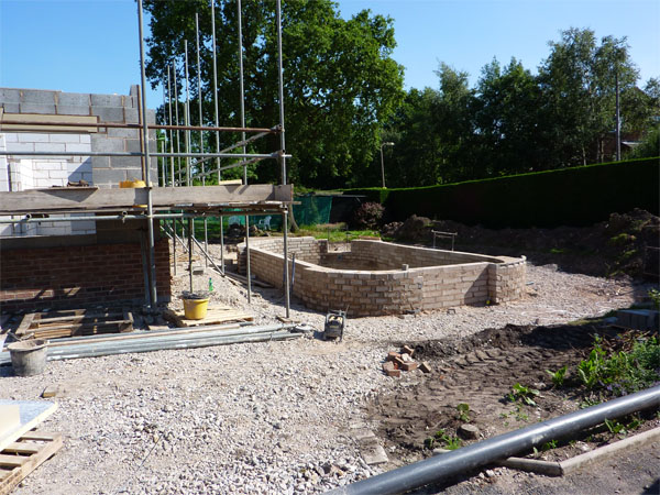
The pond walls have now been built to near final water level. This shows angled return lines fitted flush against the pond walls for cladding later.
This shows relationship of the pond to the main house. Final landscaping will cover all pond walls at a later stage.
10/07/09
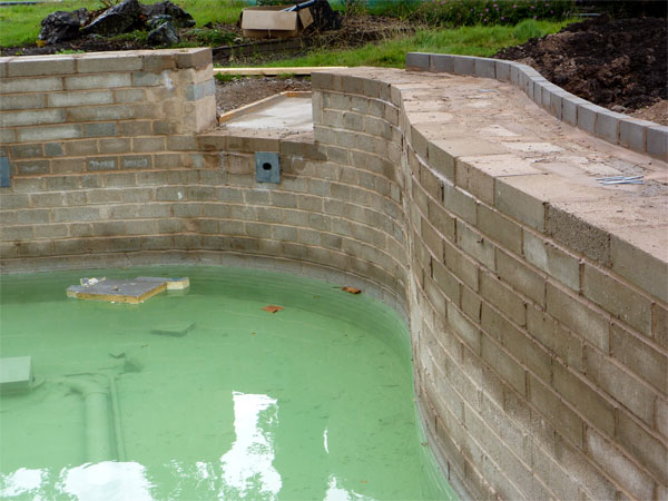
This shows the build of the top wall ledge to support the boulders to be used for landscaping the rear of the pond and to conceal the filtration area from view.
The front of the pond nearest the house will be finished with a neat, geometrical edge by way of flat stones cut to shape.
This also shows base and entry point of incoming stream from the waterfalland a waterfall bypass return for periods of cool water. The Koi willbe able to swim up this entry stream that slopes towards the pond andwill be around 30” deep at entry to the pond.
15/07/09
Underground drainage for the filters has now been completed perfectly with the necessary base plates to give perfect levels throughout.
This will allow rapid discharge of both biological and mechanical stages to waste rapidly in 4” bore lines throughout controlled by simple (and very economical) standpipes. The discharge line will eventually be connected to standard household drain lines and then taken to sewer.
20/07/09
The 4” deep base for the filtration units are now cast and all pipelines are level and fully encased as required to produce a simple flat base. This base has been made longer than required by the filters alone, this is to include a housing for all other items required such as water pumps; air pumps; U/V units and heater. The equipment housing will also have a drain at the base which is connected to the sewer line to prevent rainwater damage to the weatherproof electrical items inside. Obviously all suitable earth leakage devices will be incorporated to meet legal requirements.
The actual water level of the finished system will be just over 20” higher than this base and the area shown between pond and filter will be back-filled and then landscaped properly afterwards. This will also conceal all the 2” bore return pipelines that can also be seen here. The excavation for the small waterfall can now be seen at the far end of the filter base.
24/07/09
Walls for the three rivers has commenced in 4” solid block as shown, the equipment housing can now be seen at the far end. The outer walls only will have an extra thickness of wall when completed although this is not really necessary because of the very shallow depth (minimal weight of water) required and as the entire surrounds will be back-filled.
These three rivers are identical in dimensions but slightly wider by 2” and longer by 15” than the ‘standard’ ERIC units. This is to handle the 15% higher flow rate required in order to get the best possible ‘horizontal vacuum performance’ from the bottom drains in the pond.
On the first river (left) you can see the start of the central ‘letterbox’ transfer’ in the divider wall that now replaces the need for use of any pipe stops when discharge takes place. The incoming rush of water from 30% of the depth of the biological stage will also back-wash the brushes thoroughly and take all accumulated debris to waste in seconds via the 4” bore drains.
In terms of ‘ground volume space’ taken up in this example of a large pond system, despite having to build the boxes and walls themselves, the soil removed is positively ‘minute’ when comparing this to other filtration options around. Incidentally, apart from the standpipes themselves, no other pipe work and fittings are required in this system at all, there is not one valve required in the filter systems.
27/07/09
This is a close-up of the wall bed that will support the large rocks used in final landscaping of the pond.
These rocks will be selected on shape, size and depth from the quarry later and will require trimming to exact size before delivery. They will be installed in the pre-planned positions to fit together like a jigsaw puzzle in order to produce the desired visual effect.
The single course wall behind the bed will be waterproofed along with the rest of the pond and waterproofing will start at the rear of the wall before coming over the top of the bricks and then down to the bed itself. The pond water level will finish 1” (2.5cms) below the top of this retaining wall ensuring no water can escape. Upon completion the final ground landscaping will finish flush with the rear of the rocks and no retaining wall will be visible.
29/07/09
Update – The filter structure has now been completed, the outer walls have been built in 6” wide blocks and the inner walls in 4” wide blocks. Once again, when the area is back-filled with hardcore and topsoil, only the tops of the structures will be visible and all the walls seen here will be buried.
These 2” bore tubes seen here are pump supply lines from each river, the pumps will be positioned in this box which will also house all other items that will need to be used apart from the filter system. These items have all been detailed earlier; the box itself will have to be deeper than the filter units.
This page will be updated throughout the entire system build so please check back again shortly or subscribe to the rss feed to be notified when this page changes.
13/08/09
Work stopped on the pond until now to allow more pressing work to be carried out on the house, namely the roof!
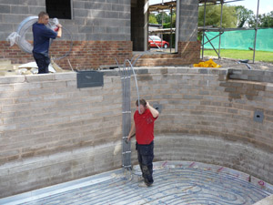
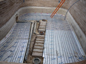
This picture shows the underfloor heating lines installed into the pond base before the final base will be cast to enclose these pipe lines and the bottom drains.
19/08/09
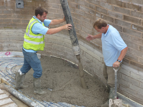
The pouring of the second base commences.
21/08/09
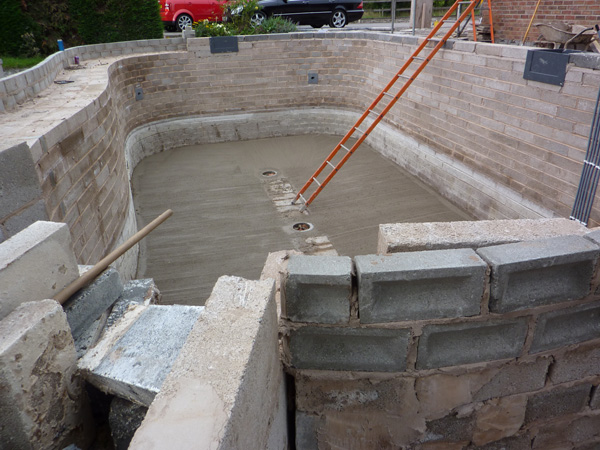
Update – these shots show the final base cast with a 5″ (12.5cms) fall from vertical pond walls to a flat central area 18″ (45cms) around the pond drains. This area is a perfect shape of the pond itself in miniature.
It also shows exit lines for the pond underfloor heating system as well as initial preparations for items to be installed into the equipment housing.
