Pond Base area Dimensions and Bottom Drains
A. The Pond Base.
As every single pond is unique in one-way or another, it is foolish to even begin to ‘generalise’ on any and all matters here. I can only begin to attempt to design a system when I have the exact pond base dimensions before me outlined on a scaled sketch. Once this is to hand, I can then work out the second most important aspect and that is the base drainage requirements after the final pond depth has been provided which then allows me to calculate total volume of the system.
Please note, I cannot even think about any filtration requirements until the first requirements have been resolved.
As we progress, this should explain for once and for all as to why it is a complete impossibility for ANY ready-made filtration supplier to come out with a statement such as:-
‘My box will filter xxxxxxxx gallons of water’
because, in truth, it is a complete impossibility! The above statement can only be made if it is followed by:-
‘subject to pond base dimensions and shape plus specific drainage facilities in your pond’
I try hard to avoid making such statements because they are only at the very best – ‘guesstimates’, although this seems to be the desired yardstick from the Koi public as to how certain ‘boxes’ perform.
As a result we get statements such as:-
‘For xxx gallons, buy this box; for xxx times 2 gallons, get this one, for xxxxx gallons you need this one’ – and so-on.
Which indicates to me that these manufacturers have no conceivable idea at all of what is required in perfect fish pond filtration today.
B. The Bottom Drain.
In 1979 I designed and produced the first ever hand-fabricated Koi pond bottom drain from UPVC which was far removed from swimming pool drains ‘sucked out’ by self-priming external motors via a 2” bore tube and the grids used by Japanese breeders in their indoor houses where outdoor debris is not present. The water sucked in from the swimming pool drain is then pumped out by the pump into a sand filter and then returned to the pool aided by chemicals. In Koi pond terms, this is a ‘pump-fed’ system. On the other hand, the pond drains in Japanese breeder’s house pond and also the filter drains are ALL connected to the drain sumps by 4” bore tube and then taken into a discharge box where they are stopped by 4” bore standpipes. The discharge box is connected to a sewer outlet and, when the standpipes are removed on a daily basis to flush away waste, the significant weight or ‘head of water’ in the pond forces the waste out with significant force and thus to sewer. These pond drains covered by grids only remove the water with some ammonia content that is directly above the grids and do not draw water horizontally from the pond base. Only 50% of ammonia-rich water produced by the Koi is taken into the filter system and the remainder is discharged to waste daily. There is a large bore (8”) ‘side feed’ in the pond wall near the base of the pond side wall and is protected by a grid on the face of the tube to prevent body damage to the Koi by suction – much more on this later.
Now back to pond drains, I produced these initially for my own use at the time because I knew they were as vital as the filter in order to start out on the road to ‘system perfection’. I think it was over one year later that someone asked me to sell him one bearing in mind that, in those days, all ponds were made by waterproof liner and few even could begin to imagine the danger in having to cut a 10” hole out of expensive butyl and thus invalidate their precious 25 year warranty given by the supplier. This was despite the fact that my drains were made with a substantial top gasket that trapped the liner between the sump and the gasket before being screwed down tightly with brass bolts into ten screw recesses ‘tapped’ into the thick UPVC ring that surrounded the sump and then were all sealed around the bolts with a mastic. I realised back then that the gasket could not really produce a perfect finish to the pond base with a liner but it was by far the best option then – when concrete ponds came along much later that problem was solved for good.
When I first installed my drains into the ponds, I discharged them via a standpipe as above on a daily basis. One of the first guys to buy my drains was George Hurst who lived locally and, after a few weeks, rang me with excitement in his voice and suggested I go over to see him immediately. On that first visit I saw for the very first time, a pond and a filter with identical water levels and a pond that contained only water and Koi. George had linked his pond to his filter via the 4” outlet from my bottom drain and the pump, the electricity supply cable and the pipe lines were all concealed at the last stage of the filter. This turned out to be the first ever example of a gravity-fed Koi pond system via a bottom drain.
To say I was impressed was an understatement and, the next day, started to convert my two systems to this method. Whilst I knew that this would mean very little to the ones starting to consider fitting a bottom drain to their precious liners and even less to them if I advised them to site water levels in pond and filter as equal; for me it was an incredible break-through and, after consideration, also knew it was a far better principle than the Japanese design as far as all-year round pond and filter operation was concerned.
The Original’ circa 1979.
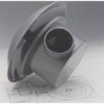 My original drains were designed and produced with a domed (mushroom) cover which was made to be 18” diameter in size, whilst the sump, including the top ring was only 12” diameter and these were purposely designed for a reason despite the cost involved back then to form these domes in an oven by slowly melting the plastic to fall around a steel mushroom shape. I chose the curved dome over the flat and cheaper option to allow debris falling onto it to be coaxed gently down to the sump itself. The ‘proper’ bottom drains on the market today are still hand-fabricated out of UPVC and the sump itself is almost identical to my original.
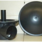 A word here, if you see today the very common ‘bottom drain’ formed by the injection-moulding manufacture process on display and offered for around 20% of the cost of the ‘proper’ item make a hasty exit if you wish your pond to operate perfectly for more than a few years. Here is a photograph of the flimsy ones I refer to and beg you not to buy if you wish to do things properly.
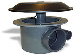 Modern-day derivative of the original
Most modern bottom drains on sale today come with a flat top (just like my ‘budget model’ I brought out in 1982) although these are generally supplied with only a 15” diameter top.
They also come fitted with various methods of air attachments to supply aeration from an air pump and thence to a circular rubber diffuser positioned above the top of the plate. Two guys who had an outlet named ‘Prokoi’ back in the late ‘80’s first introduced this to the Koi scene. A German company named Gummi-Jaeger made this specifically to keep underwater marine pipelines free from algae and detritus by way of the aeration produced.
The addition of this air rubber diffuser was to produce extra dissolved oxygen content to the pond water and thus, the flat diffuser was far easier to fit to a flat dome than the mushroom-shaped one. Some months later it was promoted with illustrations showing that the air column induced bottom water below it to be taken into the drain sump far more efficiently. To date I cannot come up with any practical experiences or evidence that this is the case although I do realise well that any increase in pond water D.O. by aeration can only be a huge benefit.
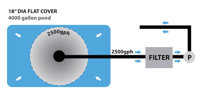
At the time of writing this, I am involved in the design and installation of a system requiring three bottom drains and have instructed the fabricator to make these with the normal air diffuser but to replace the standard 15” diameter plate with an 18” diameter plate. As to the space between the top of the sump and the underside of the top plate, this should be around 0.75” although I have used this at 0.5” with no ‘starvation’ or lack of performance even at high flow rates. If this is considered, then the enormous weight and head of water above the sump outlet and then even a 0.25” gap will perform perfectly and probably have a greater vacuum effect overall.
Before I continue I should point out that for any bottom drain to work as perfectly as is possible, it is vital, yet also obvious that the sump is installed as level as is humanly possible in order to allow suction or ‘pull’ from the entire 360 degrees of the sump top.
And now onto a subject that has never really been covered in any great detail. If it has, then I have missed it. This is the subject of how many gallons of water can one single and ‘proper’ bottom drain, correctly installed, actually process to bring about the best possible result. The majority of users consider the bottom drain to be just that – namely a drain; when in reality if it is positioned correctly at the deepest part of the pond it can be far more than just a simple drain. It is, in fact, the vital link twixt pond and filter. If the base of the pond is sloped gently to the perimeter of the top of the drain sump and also if we do not expect too much from a single drain, bearing in mind the required flow-rate through the filter which really dictates this, then our drain should ‘vacuum the pond base horizontally’ drawing its supply from the area surrounding the sump. Once again, the base area that is to be vacuumed by the ‘draw’ or the ‘pull’ of the drain is determined by the flow-rate required and applied plus the gap between sump and top cover and nothing else – with the exception of good/bad return currents and the movement of the Koi themselves which can also improve or reduce overall efficiency.
As an example, please consider a pond base of twelve feet square and pond depth of six feet deep producing a volume of 24.5 tons or approximately 5,380 gallons with the required rounded corners that has a single drain with a level 15” diameter top installed correctly in the centre and, for this example only, a slope of 3.5” to 4” from the walls to the diameter of the sump is made then this is just about an ideal situation.
-
To give a ridiculous example of flow rate here, by returning water back to the pond from the filter at 10 gallons per hour then the horizontal-flow vacuum effect on the pond base is not worth mentioning because it hardly exists.
-
Now give an equally ridiculous example whereby we pump water back from the filter at a flow-rate of 10,000 gallons per hour and then every single inch of a radius area around the centre of the base of 8 feet will be kept incredibly clean 24/7 despite the amount of mechanical debris and toxins dissolved within the water that are thrown at it.
-
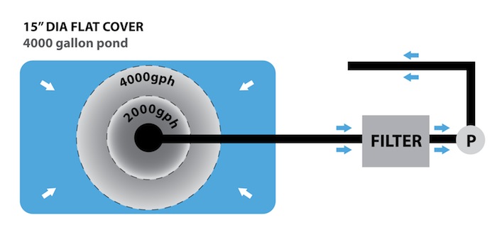
Now take this same pond with a flow rate of 2,100 gallons per hour, which turns the entire water volume over in 2.5 hours, then perhaps, an area of 6 feet diameter around the sump will be vacuumed. By using an 18” diameter top to the drain with a ‘reduced gap’ I would estimate that an area of 8 feet radius would be vacuumed.
I have given the pond turnover of once every 2.5 hours as a generalisation and it is foolish even to attempt to ‘generalise’ in the subject of optimum flow-rates and retention times through the filter system because the majority of this relates to the filtration design opted for. Filtration will be covered later in great detail.
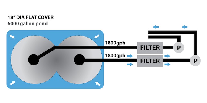
Now back to my recommended flow rate of 2,100 gallons per hour on a pond water volume of 5,300 gallons total giving a complete turnover in 2.5 hours. This pond base is 144 square feet and the best I can service it, with a single drain, an18” diameter top and a 0.5” gap is an 8 feet radius around the drain which computes to 50 square feet give or take. In short a single drain to a single outlet is not nearly sufficient in this example. We can improve this by using a drain with two 4” outlets and taking these to two independent filters and two pumps each providing a flow-rate of the same at 2,150 gallons per hour which would increase the ‘horizontal vacuum effect’ to cover and service a possible 100 square feet of pond base. The complete system turnover now is once every 1.25 hours but the flow-rate and retention time in both filters remains the same. This situation could be far better resolved by making the pond 8.75 feet wide and 16.75 feet long and this produces a similar volume of 5,400 gallons. By mentally dividing this shape equally into two parts of just over 8 feet square and putting diagonals in each square in order to get the central drain positions then two drains, in this example, would give an almost perfect result as to the cleanliness and efficiency of the drains and the base. At base sizes larger than these then more drains need to be included to perform at the same rate of efficiency.
Again, this is not a ‘cast in stone way to go’ it is an example that only applies to ponds with roughly this base dimension and fall gradients. The same shape of rectangular base with dimensions of say, 20 feet by 10 feet could be serviced by two drains with a flow rate through each filter of 2,000 gallons per hour through each filter whilst a pond base shape of ten feet by five feet could equally be served perfectly by two drains with a flow-rate through each filter of, say 1,250 gallons per hour. The flow rate can be adjusted accordingly for all similar rectangles in-between these sizes given from 5 feet by 10 feet to 8.75 feet to 16.75 feet to produce similar efficiencies. After this size it is wise to reconsider the larger base size for each application.
The ideal drainage for a perfectly circular pond (the most efficient shape and yet the most boring shape!) of up to 13 feet diameter and 6 feet deep (5,000 gallons), without doubt is a single drain dead centre to a single 4” outlet at a flow rate of around 2,000 gallons per hour. Diameters smaller than this can be regulated by flow rate. Diameters above this would mean having extra outlets to the drain sump when ordering it and then regulating flow accordingly.
Twin Outlet Bottom Drain Sump.
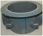 These multi-drain sumps still produce the ‘One Drain to One Filter to One Pond’ principle. In all these examples where drain performance may be on the borderline, sometimes an increase in fall to the drains can resolve the problem but the ‘gentle slope’ is better if steep falls can possibly be avoided in order to ensure the ‘horizontal vacuum’ operates properly.
Yes, the above ‘generalisations’ can be confounded in many ways as, for example, a pond of 100 feet by 10 feet by 1 feet deep (6,230 gallons) needs…………….well, you’ll know the answer by now. There is also the vague chance of a four feet diameter pond, which is 100 feet deep – do you really wish me to continue? There are thousands of similar far-fetched dimensions that can be taken into consideration but are not advised for Koi pond design.
One thing is certain in the search for perfection, this means that the pond base shape is the prime consideration followed by the position and number of drains required.
After all this has been decided by the guidelines above, then, and only then, can the filter or filters possibly begin to be considered.
I will take this one stage further by asking you to consider a 6 feet by 12 feet pond. If it is 3 feet deep it holds around 1,345 gallons; if it is 5 feet deep it holds 2,240 gallons and if it is 8 feet deep it holds 3,580 gallons. In all these examples the base dimensions and one single drain remain constant through all depths whereas the filtration requirements increase accordingly.
It is only these two factors (base dimensions and drain/s installation) that will determine just how efficiently the filter will perform.
It is obvious that the filter cannot possibly dictate how the base of the pond and the drain/s will perform, it is the base and the drainage on each individual pond that then allows us to decide on the filter/r required – please consider this because it is very important indeed in your search for perfection.
In truth, it is no more expensive to actually build a perfect system than a disastrous system if it is all considered in advance. In the long run it is far more costly to build a useless pond. It is also both simple and logical to understand because a perfect system is all just plain common sense.
As with anything in life, worthwhile new ideas and improvements to old ideas must come along with the natural progression of things and this is no different with ‘matters Koi’.
However, we must understand that the demand for ‘proper’ Koi Pond build is absolutely minute in the ‘demand’ aspect when compared to, say motor cars where the majority of buyers will opt for the latest model with all the current improvements rather than select the same model first offered for sale ten years ago. This is simply because expensive advertising will bring all this to our attention as the manufacturer is fully aware of the ‘potential’ demand for his products. As a direct opposite I am still trying to promote exactly what my 1979 bottom drain ‘is’ and ‘does’ if understood properly even today. This item and all derivatives of it must have easily sold well over a million units since then but I often wonder how many still consider it to be simply a ‘drain’. As to my ‘One drain to One filter to One pump’ principle why is this not yet accepted as ‘the only way’ since it came out in 1991? – Because, in truth it IS the only ‘proper’ way to resolve an age-old problem that has always been swept under the carpet and is still being swept under the very same carpet right now in 2009.
As I mentioned earlier, it is wrong to generalise in these matters simply because every system I have ever been involved with over the years has been unique in just about every possible detail. The real truth is there are no tailor-made solutions sitting on shelves in Koi shops the world over. Instead, it is only after purchasing the wrong items in practice, will the search become more specific and more intense to eventually come up with the goods that are perfect for your own unique system.
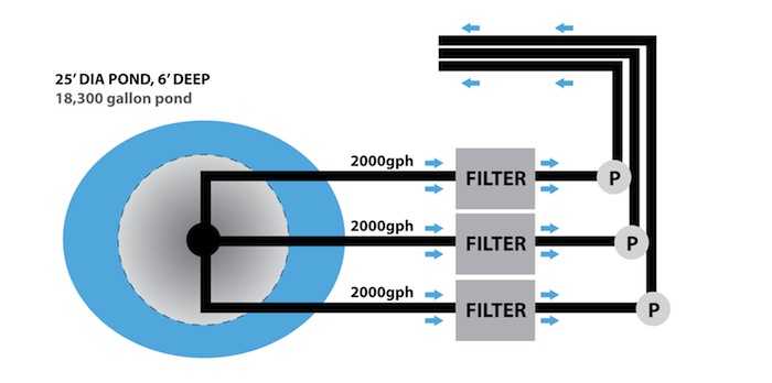
Here are a few ‘general’ diagrams, which show us just some of the layouts the reader may be considering and a few ideas, and variations of tailoring them to suit your own needs. Again, everything is based on the ‘gravity-fed’ principle. If one or two layouts prove to be even mildly useful to any reader then these have reached the desired mark. But obviously, a hundred different examples could not cover all the demands of all the enthusiasts. Again, this comes down to the individual requirements dictated by available space and other details combined to make each finished system totally unique. I do not cover actual pond surface dimensions here because I would then have to cover each depth for the same surface area thus resulting in probably four identical depths for each example and space does not allow.
Before looking at these examples, do not be under the impression that you simply switch on the pump for the first time and stand back in amazement, as the dirt on the entire pond base is ‘Whizzed Away’ in a matter of seconds, because it is not. It is, however, removed gently in part and then replaced equally as gently by more unwanted matter. Your vacuum cleaners, correctly installed, and assisted by return currents and your Koi, are working 24/7 and 365 days a year!
As a footnote, there are pond base designs that use a sloping base of the entire pond (as in swimming pools) where debris is assumed to collect at the deep area as per the attached illustration.
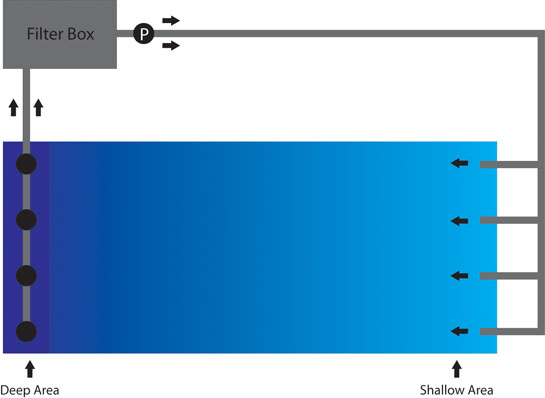 I would not recommend this method at all although I have seen this on many occasions. In this commonly-used example, it is the drain nearest to filter pick-up that takes just about all of the water supply. Even if the one drain to one filter to one pump principle is used, the distance of travel from return water to the drain pick-ups is nowhere near as efficient as the good, flat base examples shown above. It also seriously reduces the volume of water that would be possible in a flat base system.


